Tóm tắt Luận án The research on determining optimal size and layout of detetion pond for the mixed urban and agricultural basins
Trang 1

Trang 2
Trang 3
Trang 4
Trang 5
Trang 6
Trang 7
Trang 8
Trang 9
Trang 10
Tải về để xem bản đầy đủ
Bạn đang xem 10 trang mẫu của tài liệu "Tóm tắt Luận án The research on determining optimal size and layout of detetion pond for the mixed urban and agricultural basins", để tải tài liệu gốc về máy hãy click vào nút Download ở trên.
Tóm tắt nội dung tài liệu: Tóm tắt Luận án The research on determining optimal size and layout of detetion pond for the mixed urban and agricultural basins
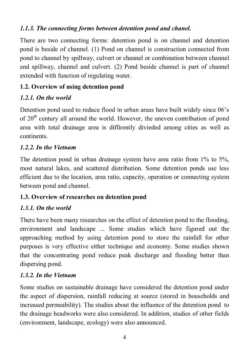
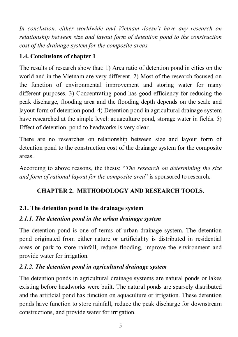
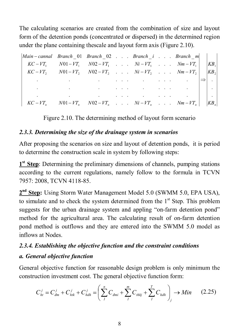
reached to a certain rate. Requirement: Determing the size and layout form of detention pond in order to minimize the construction investment cost and ensure no waterlogging corresponding the design storm. 2.3. Method 2.3.1. Proposing the sequence to solve the problem a. Traditional method It is based on experience, by calculating and direct comparision, the designers give out the best appropriate method. The steps of solving will be shown in the figure 2.9. The advantage of this method is easy to implement and the disadvantage is that the calculation volume is too large and the result depends subjectively on the proposing person. 7 b. New method The author proposes a new method to determine the size and form of rational layout for detention pond (Figure 2.8) including building objective function, solving the optimization problem by regression method, proposing a reasonable solution. Figure 2.8. New method Figure 2.9 Traditional method (Diagram of determining steps of the reasonable layout of the detention pond) The basic advantage of this proposed method is to increase the considered cases (more than 500 cases), regardless of the experience of proposer. Thus, the rationality of the proposed method is very high. 2.3.2. Facility to determine the size and layout form of detention pond The construction area should take advantage of the natural ponds and farmland and are not coincided to the technical infrastructure already planned. Proposing some different solutions: (canal, Establishing methods (hydraulic, hydrological calculating – determining designing flow rate and method scale by modelling) Establishing regression function Studing basin characteristic: Topography, geology, land using Solving multi-objective optimization problem (using empirical planningmethods to solve) Proposing selected method Proposing some solutions: (channel, detention pond) Determining the designing flow rate of each method Economy, technical calculating of each method Studing basin characteristic: Topography, geology, land using Comparing methods, determining the reasonable method Proposing selected method 8 The calculating scenarios are created from the combination of size and layout form of the detention ponds (concentrated or dispersed) in the determined region under the plane containing thescale and layout form axis (Figure 2.10). nnnnnn KB KB KB VTNmVTNiVTNVTNVTKC VTNmVTNiVTNVTNVTKC VTNmVTNiVTNVTNVTKC mBranchiBranchBranchBranchcannalMain . . . ......0201 ........... ........... ........... ......0201 ......0201 _..._...02_01_ 2 1 22222 11111 Figure 2.10. The determining method of layout form scenario 2.3.3. Determining the size of the drainage system in scenarios After proposing the scenarios on size and layout of detention ponds, it is period to determine the construction scale in system by following steps: 1st Step: Determining the preliminary dimensions of channels, pumping stations according to the current regulations, namely follow to the formula in TCVN 7957: 2008, TCVN 4118-85. 2nd Step: Using Storm Water Management Model 5.0 (SWMM 5.0, EPA USA), to simulate and to check the system determined from the 1st Step. This problem suggests for the urban drainage system and appling “on-farm detention pond” method for the agricultural area. The calculating result of on-farm detention pond method is outflows and they are entered into the SWMM 5.0 model as inflows at Nodes. 2.3.4. Establishing the objective function and the constraint conditions a. General objective function General objective function for reasonable design problem is only minimum the construction investment cost. The general objective function form: MinCCCCCCC j T 1 hdh m 1 thkj n 1 đmi j hdh j htk j đm j ht (2.25) 9 With: Cjht: The total construction investment cost of drainage system for the scenario j, Cjđm: The total construction investment cost for drainage headworks for the scenario j, Cjhtk: The total construction investment cost for conveying line (conveying cannal) for the scenario j, Cjhdh: The total construction investment cost for the detention ponds for the scenario j, J: Number of scenario J = 1, 2, 3, ..., n: Number of cannals in system, T: Number of detention pond in system. b. Constraint condition The constraint conditions in the simulation: 1) Fngập = 0; no flooding in the case of calculating rain. 2) Fhồ < (a%* Flưu vực); detention pond area is smaller than a% total drainage area. 3) Construction the detention ponds are workable. 4) Assuming the studing field has defined boundaries, planned ground of canal and pipepline, identified the slope of each channel segment, and fixed the structure form and the detention pond work in the gravity form. 5) The scenarios are siminar in work structure, unit price and calculating period. c. Establishing the objective function for studying area The identification of the objective function for the studying area is done on the basis of determining the regression function’s components. Following as 02 methods below: Method 1: Calculating directly the construction cost, establishing the regression function between construction cost and discharge. Method 2: Construction costs are taken from the project in the region. Establishing of regression function between the construction costs and discharge or area is to determine the objective function’s components. In this study, both of two ways has chosen to build the specific objective fundtion to studying areas. The order of elaboration of the regression function for each item is implemented as follows: * Drainage headwork is pumping station. The headwork of system is pumping station. The regression function corresponding to each pumps forming: 10 Cđm = f1(Qđm); (2.30) * Drainage channel system. Drainage channel system including multi-channel grade, each channel considers a representative length segment L (m). Chtk = ΣCkênh cấp 1 + ΣCkênh cấp 2 + ΣCkênh cấp 3 (2.31) * Grade 1 and 2 channels: Assuming the grade 1 and 2 channels have trapezoidal cross-section with earth channel and earth channel with embankment. The regression functions of grade 1 and 2 channels: Ck1,2 = f2(Qk1,2); (2.32) * Grade 3 channel: Most grade 3 channels’s common structure is prefabricated reinforced concrete culverts or box reinforced concrete culverts and buried underground. The regression functions of grade 3 channel: Ck3 = f3 (Qk3); (2.33a) * Detention pond: In this studying, the detention pond has function of regulating rainfall and reducing flooding. The regession function of detention pond: Chdh = f4(Fh); (2.33b) * The specific objective function: Regarding to (2.25) and (2.30, 2.31, 2.32, 2.33a, 2.33b) established, the specific objective function has following formula: C = f1(Qđm) + f2(Qk1,2) + f3(Qkc3) + f4(Fh); (2.34) 2.3.5. Applying the objective function to choose an optimal scenario a. The relationship between discharge and area of the detention pond The relationship between total peak discharge on the drainage headwork, total peak discharge on channel system and pond area is the inverse relationship. b. The relationship between total cost and pond area 11 According to the above relationships, the figure 2.26 has summersized the relationship between construction investment cost and pond area or pond’s area ratio. In where: Cđm Construction investment cost in headwork, Chtk Construction investment cost for channel system, Chdh Construction investment cost for detention pond, Cht Construction investment cost for whole system. Figure 2.26. The relationship form between construction investment cost and pond area 2.4. Conclusions of chapter 2 Using experimental planning method to solve the problem to get the results of high accuracy. The extreme points of construction investment cost that is minimum (reasonable method) depends on the construction unit prices and unit costs for site clearance compensation. When compensation unit price is higher, the extreme points will close to the origin and when construction cost is higher, the extreme points tend to back away from the origin (Figure 2.26). The methodology also presents a problem description and resolution procedures. With the method described, this methodology can be applied to all the basins where have the composite area. The Storm Water Management Model 5.0 is selected to simulate the hydrology, hydraulics for urban area, on the other hand, the on-farm pond is selected to 12 resolve to the agricultural area. Methods and tools described above are applied to specific research areas in the west of Hanoi. CHAPTER 3. RESEARCHING AND DETERMINING THE OPTIMAL SIZE AND LAYOUT OF DETENTION POND FOR THE WESTERN HANOI BASIN 3.1. Selecting and describing the research area 3.1.1. Selecting the research area The west of Hanoi is selected to be a case study for the problem of determining the size and form of detention pond. The spindle is Nhue river from the Lien Mac culvert to the Ha Dong culvert. The Dam river, Cau Nga river and La Khe river also are studied in the research. The incharging area of drainage is 17,965 ha including 13,917 ha of urban planning, 2.090ha of greenbelts planning along Nhue river, 1,958 ha of agricultural land [68]. The drainage system satisfied the data and boundary conditions, so it satisfy the requirements of the proposed problem in Chapter 2. Picture 3.1. The study area in the West of Hanoi 13 3.1.2. Features of ponds and lakes in the study area The study area has flat topography; natural ponds are few in number and small in size. The natural pond is not involved in regulating rainfall. 3.2. Validation of the Storm Water Management Model 5.0 3.2.1. Purpose To ensure the reliability of the model, consistent with the research problem, using this parameter is to simulate the scenario of the research problem. 3.2.2. Validation results Table 3.1: The evaluation table of the error of the calculating and measuring process Measuring station Daily rain Max discharge (m3/s) Total discharge (m3) Error S/ Measuring Calcu lating Error (%) Measuring Calculati ng Error (%) Hà Đông 24/8 - 28/8/2010 81,58 82,78 1,48 8.052,9 8.076,72 0,70 0,15 Đồng Quan 105,66 107,16 1,42 10.365,7 10.739,8 3,61 0,18 From table 3.1, the indicators on the maximum discharge, the total discharge and the line form are achieved. So it is possible to apply these simulations to test the model. Table 3.2: The evaluation table on the error of calculating and measuring process (02 rains) Measuring Station Daily rain Max discharge (m3/s) Total discharge (m3) Error S/ Measuring Calcul ating Error (%) Measuring Calculatin g Error (%) Hà Đông 22/5 - 26/5/2012 89,60 93,92 4,82 8.819,67 8.773,56 0,52 0,08 Đồng Quan 101,19 101,36 0,17 11.671,77 11.549,44 1,05 0,32 Hà Đông 17/8 - 19/8/2012 65,11 66,73 2,68 7.192,45 7.340,79 2,06 0,10 Đồng Quan 100,61 99,08 -0,25 11.091,29 11.022,57 0,62 0,08 From table 3.2, the error of line form is from 0.08 to 0.32, the error of maximum discharge is from 0.17% to 4.82%, the error of total discharge is from 0.52% to 2.06%. Thurs, the errors were smaller than allowance. 14 Therefore, the calculating line and measuring line is well reasionable with each other. The SWMM can be appied to calculate for this thesis. 3.2.3. The model parameters were chosen after testing a. The parameters of padded surface - Coefficient of surface roughness with hard coating: n = 0.025 – 0.15 - The parameters on the characteristics of soil permeability: Maximum permeable coefficient kmax = 8 mm/h; kmin =0.5 mm/h, the saturated seapage time is 5 days, average permeability is 25mm. b. The bed roughness coefficient: River and earth channel: n = 0.025 – 0.03; river and earth channel with embankment stone roof: n = 0.017. c. Calculating time: t = 60 s 3.3. Establishing the specific objective function for the West basin of Hanoi 3.3.1. The general objective function The Chapter 2 have determined the general objective function as following formula: C = Cđm + Chtk + Chdh = T hdh m thkj n đmi CCC 111 => Min 3.3.2.Determining the components of objective function The construction costs and the clearance price at the fourth quarter period in 2013 of the west of Hanoi to determine the components of the objective function. By considering the impact of costs for site clearance to the selection of appropriate layout scripts, author has selected 03 cases of calculations, including: TH1 (100% of agricultural land), TH2 (85% of agricultural land and 15% residential land), TH3 (70% and 30% of agricultural land for residential land). a. The drainage system headwork is pumping stations To determine the parameters in the objective function of Cđm ~ Qđm, this studying used the data of 21 pumping station in the west of Hanoi and vicinity area and updated to the cost estimates with unit price at the fourth quarter period in 2013. 15 The regression function: TH1: Cdm = 1,6578*(Qdm)1,4532; (3.4) TH2: Cdm = 1,7064*(Qdm)1,4491; (3.5) TH3: Cdm = 1,7566*(Qdm)1,4451; (3.6) With, Cdm is construction investment cost in billion Dong, Qdm is the upstream discharge in m3/s. Figure 3.18. Diagram showing the relationship of Cđm ~ Qđm b. Drainage channel system * The regression relationship between discharge and construction investment cost of the channel grade 3: The channel grade 3 usually structured as reinforce concrete round sewer or box sewer buried underground. The regression function has formula as the following table: TH The regression function at the channel grade 3 with two structural types TH1 TH2 TH3 Rectangular sewer: Ckc3 = 0,6417*ln(Qkc3) + 0,6246; (3.11) Ckc3 = 0,6764*ln(Qkc3) + 0,7114; (3.12) Ckc3 = 0,7010*ln(Qkc3) + 0,7983; (3.13) Box sewer: Ckc3 = 0,4731*ln(Qkc3) + 0,487; (3.8) Ckc3 = 0,5179*ln(Qkc3) + 0,5736; (3.9) Ckc3 = 0,5628*ln(Qkc3) + 0,6603; (3.10) Where, Ckc3 is the construction investment cost in billion Dong per 100m, Qkc3 is discharge of the channel grade 3 in m3/s. * The regression relationship between discharge and construction investment cost of channel grade 1, 2: The channel grade 1 and 2 in researching system is the trapezoidal channel. The author used the data of Nhue River to calculate for channel grade 1 and 2. The regression function for the dredged and reinforced roof channel: TH1: Cc1-2 = 0,000003*(Qc1-2)2 + 0,0032*Qc1-2 + 2,393; (3.14) TH2: Cc1-2 = 0,000003*(Qc1-2)2 + 0,0041*Qc1-2 + 2,3192; (3.15) 16 TH3: Cc1-2 = 0,000002*(Qc1-2)2 + 0,0051*Qc1-2 + 2,2455; (3.16) The regression equation for the dredged channel: TH1: Cc1-2 = 0,000003*(Qc1-2)2 + 0,0032*Qc1-2 – 0,0558; (3.17) TH2: Cc1-2 = 0,000003*(Qc1-2)2 + 0,0041*Qc1-2 - 0,1296; (3.18) TH3: Cc1-2 = 0,000002*(Qc1-2)2 + 0,0051*Qc1-2 - 0,2034; (3.19) Where: Cc1-2 Investment cost for channel grade 1 and 2 (billion/100m); Qc1-2 Designing discharge for channel grade 1 and 2 (m3/s); c. The detention pond Assuming the detention pond was built and reinforced roof by stone The regression function: TH1: Chdh = 4,8997*(Fho) + 9,7424; (3.20) TH2: Chdh = 6,2804*(Fho) + 9,7424; (3.21) TH3: Chdh = 7,6611*(Fho) + 9,7424; (3.22) Where, Chdh is construction investion and site clearance cost in billion, Fho is detention pond area in ha. The Software Eview 6.0 is applied to test the regression function on the probability of error and stability. 3.3.3. The specific regression function for the West basin of Hanoi From the general regression function and established regression function, the specific regression function has formula as following: C = f1(Qđm) + f2(Qc1-2) + f3(Qkc3) + f4(Fh) => min 3.4. Establishing the scenarios of layout of the detention ponds. Based on the literature on drainage plan for the west of Hanoi, the drainage basin is divided into 03 drainage headwork. The detention pond area selected by percentage of drainage area ranged from 0% to 6%. About detention pond layout, this study considered 03 scenario groups: (1) pond concentrated in the drainage headwork, (2) pond distributed along the main channel (PT1), (3) pond distributed along the main channel and branch channels (PT2). a. The scenarios of the detention pond concentrated at the drainage headwork (TT) 17 The author proposes 12 scenarios of the detention pond that concentrated at the drainage headwork and had the same area ratio in the 03 drainage headworks. The area ratio of detention pond ranged from 0% (no pond) to 6%. Otherwise, the authorlso proposes 24 scenarios of the different detention ponds in every drainage headworks. Totally, 36 scenarios were considered. b. The scenarios of the distributed detention pond * The scenario of detention pond distributed along the main channel (PT1) including 11 scenarios, each scenario has 11 locations of detention pond.. * The scenario of detention pond dstributed along the main channel and branch channels (PT2) including 11 scenarios, each scenario has 38 locations of detention pond. 3.5. The result 3.5.1. The results of simulation of the flow corresponding to each scenario The discharge in calculating or modeling is the average value in hour. According to designing standard, this value will be used in designation. 3.5.1.1. The scenarios of the detention pond concentrated at the drainage headwork (TT) Figure 3.10. The relationship between upstream discharge and the detention pond area Figure 3.11. At Lien Mac inflow when the detention pond area changing At the upstream, discharge decrease when the pond area increases. The reduction is smaller and smaller (Figure 3.10 and 3.11). The peak discharge summary of the headworks reaches to minimum at TT666 (pond ratio 6%). When the pond area ratio is different at the headworks, the headwork discharge 18 summary reaches to minimum corresponding to pond ratio 5.3% (as scenario TT664). 3.5.1.2. The scenarios of the distributed detention pond The calculation results for the scenario group (PT1) and (PT2) present the total peak discharge at upstream and total peak discharge at channels are minimum when the pond ratio is 4.35% (as scenario PT1-6) and 4.58% (as scenario PT2-6) corresponding to the scenario groups PT1 and PT2. 3.5.1.3. Comparision between scenarios of concentrated and distributed detention pond The comparision is shown in the following diagram: Figure 3.15. The diagram of relationship between upstream discharge and the detention pond area Figure 3.16. The diagram of relationship between the total of peak discharge and the detention pond area The headwork peak discharge reduces in all 3 scenario groups (TT, PT1 và PT2). In which, the scenario of distributed detention pond along the main chaneel and branch channel (PT2) gave out the minimum value (figure 3.15). The diagram 3.16 has shown that the peak discharge of the channel system corresponding to scenario (TT) unchanged (horizontal line). On the other hand, both of the scenarios (PT1) and (PT2) decreased strongly. Especially, the scenario of pond distributed along the main channel and branch channels have strongest reduction (the pink line) Summary: Regulating effect of the pond depends on not only the pond scale, but also the form layout (concentrated or distributed). Considering overview of the system, if the distribution of detention pond is more and more large, the effect of peak di
File đính kèm:
 tom_tat_luan_an_the_research_on_determining_optimal_size_and.pdf

