Luận án Isogeometric finite element method for limit and shakedown analysis of structures
Trang 1
Trang 2
Trang 3
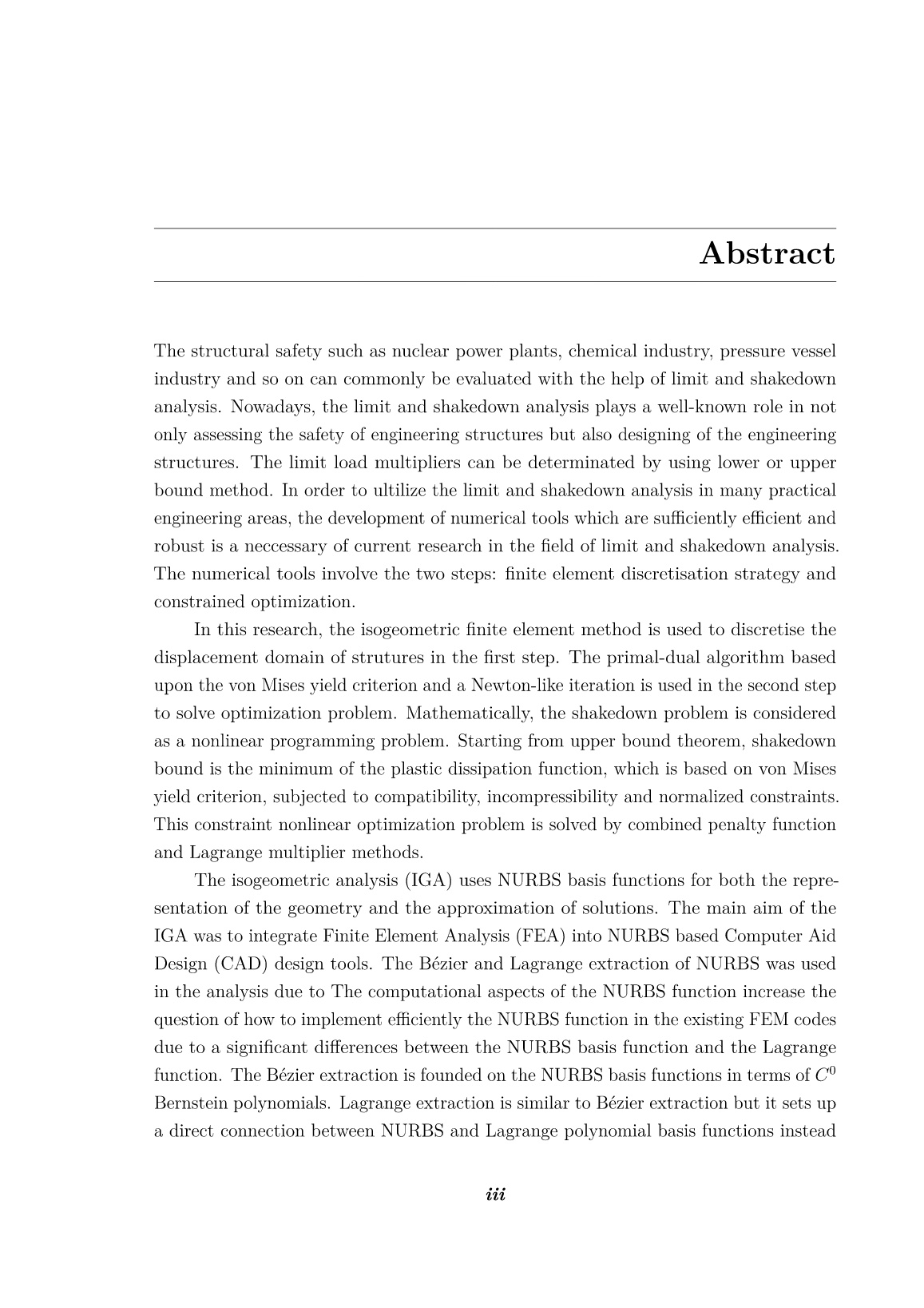
Trang 4

Trang 5
Trang 6
Trang 7
Trang 8
Trang 9
Trang 10
Tải về để xem bản đầy đủ
Bạn đang xem 10 trang mẫu của tài liệu "Luận án Isogeometric finite element method for limit and shakedown analysis of structures", để tải tài liệu gốc về máy hãy click vào nút Download ở trên.
Tóm tắt nội dung tài liệu: Luận án Isogeometric finite element method for limit and shakedown analysis of structures
.8, 1, 1, 1
]
3.4 A brief of NURBS based on Bézier extraction 50
is shown in Fig 3.15. As a result, the number of control points and of basis functions
increase equivalently.
0 0.25 0.5 0.75 1
0
0.2
0.4
0.6
0.8
1
(a) Ξ =
[
0, 0, 0, 0.25, 0.5, 0.75, 1, 1, 1
]
0 0.25 0.5 0.75 1
0
0.2
0.4
0.6
0.8
1
(b) Ξ =[
0, 0, 0, 0.25, 0.25, 0.5, 0.75, 1, 1, 1
]
0 0.25 0.5 0.75 1
0
0.2
0.4
0.6
0.8
1
(c) Ξ =[
0, 0, 0, 0.25, 0.25, 0.5, 0.5, 0.75, 1, 1, 1
]
0 0.25 0.5 0.75 1
0
0.2
0.4
0.6
0.8
1
(d) Ξ =[
0, 0, 0, 0.25, 0.25, 0.5, 0.5, 0.75, 0.75, 1, 1, 1
]
Figure 3.15: Bézier decomposition of
Ξ =
[
0, 0, 0, 0.25, 0.5, 0.75, 1, 1, 1
]
3.4.2 Bézier extraction [75; 76; 95] of NURBS
Supposedly, a B-spline curve has a knot vector Ξ =
[
ξ1, ξ2, ..., ξn+p+1
]
and a set of
control points P = {Pi}ni=1. It allows us to gain m new control P = {P¯i}mi=1 from the
3.4 A brief of NURBS based on Bézier extraction 51
original control points P = {Pi}ni=1 as
P¯i =
P1 i = 1
αiPi + (1− αi)Pi−1 1 ≤ i ≤ m
Pm i = m
(3.30)
Let {ξ¯1, ξ¯2, ...ξ¯j, ξ¯m} be a set of knots inserted in Bézier decomposition. Let αji , i =
1, 2, ..., n + j, be ith component of α to jth knot inserted for each new knot ξ¯j; j =
1, 2, ...,m. αi defined as
αi =
1 1 ≤ i ≤ k − p
ξ¯ − ξi
ξi+p − ξi k − p+ 1 ≤ i ≤ k
0 i ≥ k + 1
(3.31)
Now, defining Cj in [71].
Cj =
α1 1− α2 0 ... 0
0 α2 1− α3 0 ... 0
0 0 α3 1− α4 0 ... 0
... ... ... ...
0 ... 0 αn+j−1 1− αn+j
(3.32)
In matrix form, Eq. 3.30 can be written by knot insertion process as
P¯ j+1 =
(
Cj
)T
P¯ j (3.33)
where P¯ 1 = P . The final set of control points is a new set of Bézier ones
CT =
(
Cm
)T(
Cm−1
)T(
C1
)T
(3.34)
Consequently, the relation between new Bézier control points and original B-spline ones
has the following form
P b = CTP (3.35)
where C is called the Bézier extraction operator. The B-spline curve is from
x
(
ξ
)
= P TN
(
ξ
)
(3.36)
3.4 A brief of NURBS based on Bézier extraction 52
and after inserting knots, B-spline curve with Bézier points becomes:
x
(
ξ
)
= x
(
P b
)T
B
(
ξ
)
= P TCB
(
ξ
)
(3.37)
From Eqs. 3.36 and 3.37 one obtains
N e
(
ξ
)
= CeB
(
ξ
)
(3.38)
In Eq. 3.38, the B-spline basis functions are equal to the Bernstein polynomials through
Ce; where Ce is a Bézier extraction operator, e denotes the element number and B
(
ξ
)
are Bernstein polynomials which is in bi-unit interval
[
− 1 1
]
as follows:
Bi,p
(
ξ
)
= 12
(
1− ξ
)
Bi,p−1
(
ξ
)
+ 12
(
1 + ξ
)
Bi−1,p−1
(
ξ
)
(3.39)
where
B1,0
(
ξ
)
≡ 1 and Bi,p
(
ξ
)
≡ 0 if i p+ 1 (3.40)
-1 -0.5 0 0.5 1
0
0.25
0.5
0.75
1
(a) p = 1
-1 -0.5 0 0.5 1
0
0.25
0.5
0.75
1
(b) p = 2
-1 -0.5 0 0.5 1
0
0.25
0.5
0.75
1
(c) p = 3
-1 -0.5 0 0.5 1
0
0.25
0.5
0.75
1
(d) p = 4
Figure 3.16: The Bernstein polynomials for polynomial degree p
= 1, 2, 3 and 4.
3.4 A brief of NURBS based on Bézier extraction 53
The Bernstein polynomials are also symmetric and interpolatory at the endpoints,
similar to the Lagrange polynomials. The ith derivative is
d
dξ
Bi,p
(
ξ
)
= p2{Bi−1,p−1
(
ξ
)
−Bi,p−1
(
ξ
)
} (3.41)
On the result in Eq. 3.36, a NURBS curve can be written as
x
(
ξ
)
= 1
W
(
ξ
)P TWCN(ξ) = 1
W
(
ξ
)P TWCB(ξ) = 1
W
(
ξ
)(CTWP)TB(ξ)
(3.42)
where W are the NURBS weights. The weight function W
(
ξ
)
is written as follows
W
(
ξ
)
= wTN
(
ξ
)
= wTCB
(
ξ
)
=
(
wb
)T
B
(
ξ
)
= W b
(
ξ
)
(3.43)
where wb are the Bézier weights and are computed
wb = CTw (3.44)
Similar to Eq. 3.36, a NURBS curve in terms of Bézier points becomes
x
(
ξ
)
= 1
W b
(
ξ
)(P b)TW bB(ξ), (3.45)
where W b is the Bézier weights. Comparing Eqs. 3.42 and 3.45, the relation between
the Bézier control points and the NUBRS control points are obtained as
P b =
(
W b
)−1
CTWP (3.46)
The NURBS basis functions for element e using the Bézier extraction operator become
Re
(
ξ
)
=
W eN e
(
ξ
)
W b
(
ξ
) = W eCeBe
(
ξ
)
W b
(
ξ
) (3.47)
Extraction operator of surface and solid works in the same manner as the NURBS curve
as follows:
Ce = Ce
(
ξ
)
⊗Ce
(
η
)
(3.48)
and
Ce = Ce
(
ξ
)
⊗Ce
(
η
)
⊗Ce
(
ζ
)
(3.49)
3.5 A brief review on Lagrange extraction of smooth splines 54
where Ce
(
ξ
)
,Ce
(
η
)
and Ce
(
ζ
)
are the univariate elemental Bézier extractors in the
ξ, η and ζ direction.
3.5 A brief review on Lagrange extraction of
smooth splines
A detail of Lagrange extraction based on smooth splines is presented in the work
of Dominik Schillinger et al. [77]. We present an overview of this process which
decomposites a smooth piecewise polynomial B-spline basis into a C0 nodal Lagrange
basis.
3.5.1 Lagrange decomposition
A B-spline curve C(ξ) as shown in Fig 3.17 (a) is defined by a linear combination
of B-spline basis functions Ni,p and corresponding set of vector-valued control points
Pi over the parametric space as follows:
C(ξ) =
n∑
i=1
Ni,p(ξ)Pi = P TN (ξ) (3.50)
P1
P2 P3
P4 P5
P6
(a) B-spline curve and B-spline control points.
N1
N2 N3 N4 N5
N6
+1
e
+2
e
+3
e
(b) Corresponding cubic B-spline basis.
Figure 3.17: Smooth C2-continuous curve represented by a B-spline basis
The parametric space which is used to define the B-spline basis function can be
derived into knot spans as elements Ωˆe in the isogeometric analysis as depicted in Fig
3.5 A brief review on Lagrange extraction of smooth splines 55
3.17 (b). We now concentrate on a single element e and establish this element to a new
parametric coordinate ξ ∈ [−1, 1] . The element is supported (p + 1) B-spline basis
functions created a linearly independent and complete polynomial basis up to degree p.
We can represent the B-spline basis functions in another form which is based on a linear
combination of the basis functions of any other polynomial basis and complete up to
polynomial degree p. The nodal Lagrange basis functions satisfies these two properties.
For each B-spline function, we can therefore write
N ea,p(ξ) =
p+1∑
b=1
αabLb,p(ξ) (3.51)
or in matrix form
N e(ξ) = DeL(ξ) (3.52)
L1 L2 L3
L4
L5
L6 L7
L8
L9
L10 L11 L12
+1
e
+2
e
+3
e
(b) Corresponding cubic nodal basis.
(a) Lagrange curve and Lagrange control points.
Ll1
Ll2
Ll3 Ll4 ,L
l
5
Ll6
Ll7
Ll8 ,L
l
9
Ll10 L
l
11
Ll12
Figure 3.18: Smooth C2-continuous curve represented by a nodal Lagrange basis
and after inserting Eq. (3.52) into Eq. (3.50), the B-spline curve segment with
nodal Lagrange points in Eq. (3.50) becomes
C(ξ)e =
(
P e
)T
N e(ξ) =
(
P e
)T
DeL(ξ) =
(
P l,e
)T
L(ξ) (3.53)
3.5 A brief review on Lagrange extraction of smooth splines 56
where L(ξ) = La,p(ξ)p+1a=1 in Eqs. (3.52, 3.53) is a standard Lagrange basis functions
which are identical in each element and associated nodal points ξˆa on the element e.
Unlike B-splines basis functions which are required index e due to a difference in each
element, the Lagrange basis functions are the same in each element. Therefore, they
do not require an index e. De, containing the coefficients αab, is a Lagrange extraction
operator for element e. From Eq. (3.52), we can also see that the element B-splines
functions are equal to the Lagrange basis function through De. Eq. (3.53) also shows
the relationship between the Lagrange and the smooth B-spline control points as follows:
P l = DTP (3.54)
Fig. 3.18 (a) shows the Lagrange control points and the new curve represented by
Lagrange basis functions which is the same as the B-splines one as shown in Fig 3.17 (a).
Fig 3.18 (a) also shows that this curve remains higher-order continuity between curve
elements in spite of C0 continuous Lagrange shape functions at element boundaries.
The cubic Lagrange basis functions are shown in Fig 3.18 (b) over each element.
3.5.2 The Lagrange extraction operator
In this subsection, the computation of the Lagrange extraction operator is presented
by using its interpolatory property at the nodal points ξˆa [96].
La,p
(
ξˆa
)
=
1 if a = b0 if a 6= b (3.55)
Fig. 3.18 (b) illustrates an examples of the interpolatory property at element nodes.
An interpolation u¯(ξ) of a function u(ξ) can be obtained by using Eq. (3.55) with nodal
basis functions La,p as follow
u¯(ξ) =
p+1∑
a=1
La,pu(ξˆa) (3.56)
From Eq.(3.55) and (3.56), the coefficients of De in the ath row in Eq. (3.52) can be
obtained by evaluating the corresponding N ea,p at all element nodes {ξˆb}p+1b=1 . The full
Lagrange extraction operator, De, for 1D element can be expressed as
Deab = N ea,p
(
ξˆb
)
, {a, b} = 1, ..., p+ 1 (3.57)
3.5 A brief review on Lagrange extraction of smooth splines 57
or in matrix form
De =
N e1,p(ξˆ1) N e1,p(ξˆ2) ... N e1,p(ξˆp+1)
N e2,p(ξˆ1) N e2,p(ξˆ2) ... N e2,p(ξˆp+1)
... ... ...
N ep+1,p(ξˆ1) N ep+1,p(ξˆ2) ... N ep+1,p(ξˆp+1)
(3.58)
This subsection demonstrated the concept of one-dimensional Lagrange extraction
operator. A multi-dimensional one can be constructed by evaluating tensor-product
B-spline functions at nodal points. Summary of the element-level transformation
connections between B-spline and Lagrange basis functions is shown in Fig 3.19. An
example of the element-level transformation for 2D case is shown in Fig. 3.20.
Smooth B-splines
-1 1
Nodal basis (Lagrange)
D
D-1
Figure 3.19: Demonstration of the Lagrange extraction operators in 1D case and
their inverse for the transformation of B-spline, Lagrange on an element level. The
second B-Splines element of the example curve is shown in Fig 3.17
3.5.3 Rational Lagrange basis functions and control points
NURBS can represent some conic shapes such as circles and ellipsoids exactly
while B-Spline cannot represent these shapes. NURBS basis functions on each element
e, Re(ξ) = {Rea,p(ξ)}p+1a=1, can be defined as
Rea,p(ξ) =
waN
e
a,p(ξ)
W (ξ) (3.59)
where wa are weights of the ath basis function. The weight function W is expressed as
W (ξ) =
p+1∑
b=1
wbN
e
b,p(ξ) (3.60)
3.5 A brief review on Lagrange extraction of smooth splines 58
We can rewrite Eq. (3.59) in matrix form
R(ξ) = 1
W (ξ)WN (ξ) (3.61)
where W is the diagonal matrix of weights defined as
W =
w1
w2
. . .
wp+1
(3.62)
The NURBS curve in matrix form can be written as
C(ξ) = PTR(ξ) = 1
W (ξ)P
TWN (ξ) (3.63)
Substituting Eq. (3.52) into Eq. (3.63), the NURBS curve becomes NURBS curve in
terms of the nodal Lagrange basis functions as follows
C(ξ) = 1
W (ξ)P
TWDL(ξ) = 1
W (ξ)(D
TWP)TL(ξ) (3.64)
The weight function W (ξ) in Eq. (3.68) is written in matrix form as
W (ξ) = wTN (ξ) (3.65)
In terms of the nodal Lagrange basis, the weight function becomes
W (ξ) = wTDL(ξ) = (DTw)TL(ξ) = (wl)TL(ξ) = W l(ξ) (3.66)
where w = {wa}p+1a=1 is a weight vector associated with NURBS basis function while
wl = DTw is a weight vector associated with the Lagrange basis functions.
W l =
wl1
wl2
. . .
wlp+1
(3.67)
3.5 A brief review on Lagrange extraction of smooth splines 59
By defining the diagonal matrix W l in Eq. (3.67), the Lagrange control points can be
computed as
P l = (W l)−1DTWP (3.68)
This equation shows the connection between the Lagrange control points and the
NURBS ones. We obtain the new form by multiplying W l to both sides in Eq. (3.68)
as
DTWP = W lP l (3.69)
Substituting Eq. (3.69) into Eq. (3.64), we finally obtain the Lagrange representation
of a NURBS curve.
C(ξ) = PTR(ξ) = 1
W (ξ)P
TWN (ξ) = 1
W (ξ)(D
TWP)TL(ξ)
= 1
W l(ξ)(P
l)TW lDL(ξ) =
n∑
a=1
wlaLa,p(ξ)
W l(ξ) P
l
a (3.70)
(a) Quadratic NURBS shape
function with knot value
𝚵 = {0 0 0 0.5 1 1 1}
𝐇 = {0 0 0 0.5 1 1 1}
(b) Quadratic NURBS shape
function for one element in the
range parametric value [0 0.5] in
both directions.
(c) Quadratic Lagrange basis shape
function for one element
D-1
D
Figure 3.20: Demonstration of the Lagrange extraction operators in 2D case and their
inverse for the transformation of NURBS and Lagrange on an element level. The first
NURBS element of 2D case example is shown in Fig. 3.20(a)
In summary, each segment of a smooth NURBS curve can be equivalently repre-
sented by a set of C0 nodal Lagrange elements. Note that the Lagrange representation
of the NURBS curve still remains smoothness between curve segments in spite of the
C0 continuity of the nodal basis functions at element boundaries.
3.5 A brief review on Lagrange extraction of smooth splines 60
3.5.4 Using Lagrange extraction operators in a finite element code
After using a CAD tool to design the analyzed geometric object, we generate
the data included Lagrange elements, control points P l, weights W l and extraction
operators D. These information are stored for each element separately. In element-level
subroutines, we can use a standard nodal FEM code to compute the element stiffness
matrix keFEA and the element load vector f eFEA. Then, we use Lagrange extraction
operator to compute the IGA element stiffness and load vector in Eqs. (3.71, 3.72) to
transform the C0-continuous Lagrange to the NURBS element before assembly into the
global arrays.
keIGA =
(
De
)
keFEA
(
De
)T
(3.71)
f eIGA =
(
De
)
f eFEA (3.72)
where keIGA and keFEA are the element stiffness matrices and f eIGA and f eFEA are the
element force vectors for the smooth spline case and C0 continuous Lagrange case,
respectively.
4
THE ISOGEOMETRIC FINITE
ELEMENT METHOD APPROACH TO
LIMIT AND SHAKEDOWN ANALYSIS
4.1 Introduction
In general, the problem of limit and shakedown analysis can be transformed into an
issue of mathematical nonlinear programming. In this chapter, the integrations in Eq.
(2.53) is transformed into summation forms, which are based on two discreatizations as
follows:
• Load domain discretization: the integration over a certain time interval t ∈
[
0, T
]
is transformed into a summation form for k = 1,m, where k is a loading vertex
and m = 2n is a number of vertices in the load space, n is the number of variable
loads.
• Isogeometric finite element discretization: the integration over the entire structure
Ω is transformed into the numerical integration for i = 1, NG, where i is a
Gaussian point and NG is the number of Gaussian points in the structure.
With these discretizations, the limit and shakedown analysis is reduced to checking the
restrictions only at all load vertices m and all Gaussian points NG instead of checking
for the entire load domain L and the entire structure Ω.
Studying the lower bound theorem of Melan [16], Belystchko [19] showed that if
the static shakedown condition is statisfied for all corners of the given convex polyhedral
load domain then it will be satisfied for any load path within this domain. According
61
4.2 Isogeometric FEM discretizations 62
to the von Mises yield criterion and this remark, the shakedown limit load factor is
introduced as a nonlinear optimization problem by Belystchko [19]. Based on the static
theorem of Melan [16], Corradi et al. [97] improved Maier’s work which analyzed the
shakedown problem by linear programming with large number constraints to less linear
inequality constraints, applied in numerical computations and obtained a primal static
formulation as well as its dual kinematic version through duality properties. Dualities
and convergence in limit and shakedown analysis were studied by Morelle [89; 90],
Nguyen [98], Xue et al. [99], Xu et al. [100],...They focused two different kinds of
duality in shakedown.
Discrete formulations of lower bound methods for perfectly plastic structures have
been presented by some researchers such as: Hachemi et al. [101], Weichert [102], Le et
al. [48] and so on. A primal dual approach to the discretization of the upper and lower
bound method has been presented for perfectly plastic structures by some researchers:
Vu. D. K [28], Yan [98], Do [54],.... A mainly extend Vu’s discrete formulation of the
upper bound method based on isogeometric analysis is investigated.
In this chapter, some problems are studied as below:
• The discretized formulations of limit and shakedown using isogeometric finite
element method.
• The duality between upper bound and lower bound of shakedown limit load factor.
• The dual procedure for limit and shakedown analysis algorithm between the upper
bound and lower bound.
4.2 Isogeometric FEM discretizations
4.2.1 Discretization formulation of lower bound
As we know in analysis of solids, by appying the principle of virtual work presented
in Section 2.2.2 to the equilibrium equations we obtain their corresponding "weak form"
and this "weak form" can be discretized by mean of the isogeometric finite element
method.
First of all, the Eq. (2.24), the principle of virtual work equation, can be rewritten
in matrix form: ∫
Ω
σδεTdΩ =
∫
Ω
gδuTdΩ +
∫
Γt
qδuTdΓt (4.1)
The virtual displacement δu within an element e is approximated by interpolation
of control point values:
δu =
ne∑
l=1
Nlδu
e
l (4.2)
4.2 Isogeometric FEM discretizations 63
whereNl and uel are the lth shape function matrix and the vector of virtual displacements
of the lth control point of the IGA element e which has ne control points. The virtual
strain δε is derived by:
δε = ∂δu = ∂N
(
x
)
δue = B
(
x
)
δue (4.3)
Note that B
(
x
)
= ∂N
(
x
)
is a deformation matrix. Eq.(4.3) is called strain-
displacement relation or relation of upper bound and lower bound method.
By subdividing the whole volume Ω into ne elements Ωe. By using Eqs.(4.2), (4.3) and
some manipulations, the integration Eq.(4.1) has the following form:
ne∑
e=1
ng∑
i=1
wiB
eT
i σi =
ne∑
e=1
f e (4.4)
The Eq. (4.4) in elastic behaviour case becomes as follow
ne∑
e=1
ng∑
i=1
wiB
eT
i σ
E
ik =
ne∑
e=1
f ek (4.5)
where
• Bei is the deformation matrix B
(
x
)
at Gauss point xi of element Ωe.
• f e is force vector of element e.
• wi is the weight factor of the Gauss point i.
• ne is the total number of elements in Ω
• ng is the total number of integration Gauss points in each element Ωe.
• σEik defines the fictitious elastic stress vector at Gauss point i corressponding to
the load domain vertex Pˆk and is computed by σEik = EeBeiuek.
• f ek is force vector of element e coressponding to the load domain vertex Pˆk.
• Ee is elastic modul matrix of the element e.
By integration on the whole elements using the Gauss-Legendre integration technique,
the Eq.(4.5) can be expressed as follow:
NG∑
i=1
wiB
eT
i σ
E
ik =
ne∑
e=1
f ek (4.6)
4.2 Isogeometric FEM discretizations 64
where NG = ne× ng is total number of Gaussian point on whole domain.
For residual stress, the Eq.(4.6) can be written as
NG∑
i=1
wiB
eT
i ρ¯i = BT ρ¯ = 0 (4.7)
where B is the global deformation matrix and ρ¯ denotes the global residual stress
vector. They have the following form:
B =
[
w1B1, w2B2, ..., wiBi, ..., wNG−1BNG−1 , wNGBNG
]
(4.8)
ρ¯T =
[
ρ¯T1 , ρ¯
T
2 , ..., ρ¯
T
i , ..., ρ¯
T
NG−1 , ρ¯
T
NG
]
(4.9)
Because the value of the residual stress ρ¯ is calculated at Gaussian point, the discretized
necessary limit and shakedown conditions at Gaussian point i can be represented by:
f
(
ασEik + ρ¯i
)
≤ 0 ∀k = 1,m ∀i = 1, NG (4.10)
By using Eq.(2.24), the lower bound of the shakedown load multiplier presented in Eq.
(2.37) may be written as:
α− = max α (a)
subjected to: (4.11)
∫
Ω
δεij(x)∂j ρ¯ij(x)dΩ = 0 in Ω (b)∫
Ω
δεij(x)σEij(x, Pˆk)dΩ =
∫
Ω
fi(x, Pˆk)u˙idΩ +
∫
Γt
t¯i(x, Pˆk)u˙idΓt on Γt (c)
f
(
ασEij
(
x, Pˆk
)
+ ρ¯ij(x)
)
≤ 0 ∀k = 1,m (d)
Finally, the lower bound of limit and shakedown load factor which is based on Eq.(4.11),
(4.7) and (4.File đính kèm:
 luan_an_isogeometric_finite_element_method_for_limit_and_sha.pdf
 Trang thong tin LA tieng Anh Do Van Hien 24_06_2020.docx
 Trang hong tin LA tieng viet Do Van Hien 24_06_2020.docx
 Tomtat luan an tieng Viet_NCS Do Van Hien 24_06_2020.pdf
 Tomtat luan an tieng Anh_NCS Do Van Hien 24_06_2020.pdf

